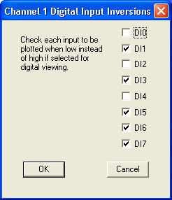
This function displays the digital input channel as a digital sub-channel featuring each individual bit.
The default display shows a bar for each data point that contains at least one high signal. If the signal you wish to monitor is usually high, the bar can be inverted so it is displayed for each data point that contains at least one low signal.
When this function is enabled, the selected digital input channel is displayed as a digital plot with each individual bit (digital inputs 0 through 7) displayed as a solid bar, and a check mark is displayed on the Scaling menu immediately preceding the Digital Plot… command.
Enable a digital plot:
![]() In
the Scaling menu click on Digital Plot….
In
the Scaling menu click on Digital Plot….
![]() Choose
Scaling Digital Plot… (ALT, C, T).
Choose
Scaling Digital Plot… (ALT, C, T).
This displays the “Channel X Digital Input Inversions” dialog box (where X represents the enabled channel, in this example it is channel 0).

Use this box to invert the digital input bit line display to accommodate your preference. The default configuration, shown by a check mark in the desired digital input box, is a dark line on a light background for a high signal condition and no line for a low signal condition. Clicking in the digital input box removes the X and inverts the line display (a light line on a dark background for a high signal condition and no line for a low signal condition). Multiple combinations are possible.