|
|
|
|
Stand-alone Setup > Channel Settings |
|
Enable/disable channels by left-clicking in that channel's channel box.
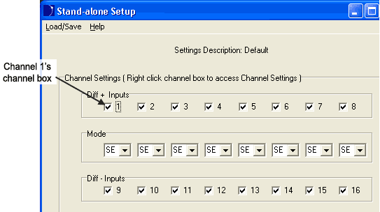
A Checkmark denotes that the channel is enabled. An empty box indicates the channel is disabled. Right-click in any channel box to bring up the channel settings dialog for that channel.
Note: You MUST have your instrument connected properly to access the Channel Settings dialog box.
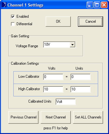
The Channel Settings box allows you to enable/disable channels, set channels as differential or single-ended, change the Voltage Range (Gain Setting), and calibrate the channel to significant engineering units. Use the Previous Channel and Next Channel buttons to go to the next/previous channel's Channel Settings box. Use the Set ALL Channels box to copy the displayed channel settings to all analog input channels.
Enabling a Channel as Differential
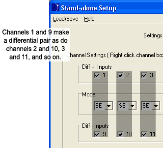
The Channel Settings Frame is configured to show Differential Input pairs (+ and -). The Diff + Inputs represent the positive differential channels while the Diff - Inputs represent their negative counterparts. Each negative differential channel is directly below its positive counterpart.
To set a channel as differential click on the drop-down box directly below that channel's channel box. Options are SE for single-ended operation or DIF for differential. Click on DIF. Immediately, its negative counterpart will be displayed as differential.
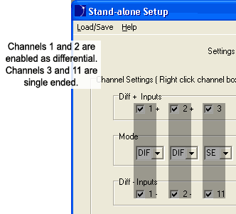
When Mode is set to DIF, both channels in a differential pair must be enabled or disabled. Left-clicking in either channel's Channel box will enable or disable the pair.
Setting the Voltage Range (Gain)
The Voltage Range drop-down box in the Channel Settings window allows a Gain to be associated with each channel. Gain allows you to fine-tune the output resolution of a particular waveform. For example, if your instrument is a DI-710-UHS, and you know your inputs will be between +5 Volts and -5 Volts, use a Voltage Range of 5V (gain setting of 2). Use the following table to determine which gain settings are available with your instrument.
|
Models |
DI-710-UHS and -EHS DI-715B-US and -ES |
DI-710-ULS and DI-710-ELS |
||||||
|
Gain |
1 |
2 |
4 |
8 |
1 |
10 |
100 |
1000 |
|
Voltage Range |
±10V |
±5V |
±2.5V |
±1.25V |
±10V |
±1V |
±0.1V |
±0.01V |
To set the Voltage Range click on the drop-down box and select the desired setting. Note: The DI-718B and DI-718Bx have no Gain settings.
Calibrating a Channel to Engineering Units
As long as any two voltage equivalents are known, each channel may be calibrated to significant engineering units using the Calibration Settings available in the Channel Settings Window.
To calibrate a channel:
For example, if you have the following Input/Output equivalents (on a DI-5B47K-13 the following chart is located on the back of the 5B module):
Input: -100ºC +1350ºC
Output: 0V +5V
Using the above example, the Channel Settings Window would look like this:
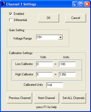
In the above example, the Gain Setting may be changed to 2 (5V) to better represent the waveform.
Note: ANY two voltage equivalents may be used.