Additional Reading:
4-20 mA Shunt Resistor and Current Loop Data Acquisition Products
I estimate that 20-30 percent of measurements made by our customers are from 4-20 mA current loop sensors and systems. If you draw a blank after reading this first sentence, see this and this for some 4-20 mA background information. One question that arises quite often is how to calculate measurement resolution in applied engineering units when measuring 4-20 mA current loops. In this post, I’ll show you how to make this calculation in four easy steps by using a hypothetical 0-1,000 psi load cell with a 4-20 mA output.
Step 1 – 4-20 mA current loop is ‘volts’ by any other name
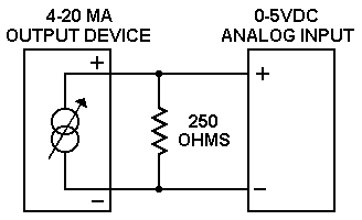
Many are surprised to learn that devices that measure current do not make a direct measurement. Instead, current is always an indirect measurement that produces a voltage output that’s proportional to applied current. In 4-20 mA current loop applications, this is almost always accomplished by applying a shunt resistor of known resistance in series with the current loop, and then measuring the voltage across it with a voltage measurement device like a data logger or data acquisition system. A typical shunt resistor value (and the one I’ll use in our example) is 250 Ohms, since it develops a nice, round voltage drop of 1 Volt for 4 mA and 5 Volts for 20 mA of applied current.
So, Step 1 is the simple application of Ohm’s Law (V=IR) to determine the voltage drop across the shunt resistor. In our example, V=(0.004)(250)=1 and V=(0.020)(250)=5.
Step 2 – Calculate consumed measurement range
We know that the 4-20 mA current measurement will produce a voltage measurement with a span of 4 volts (5-1). Now we need to calculate how much this span consumes as a percentage from the total measurement range of the device we use to make it. Let’s assume that we use a DI-149 Data Acquisition Starter Kit for the measurement that has a fixed measurement range of ±10 VFS (volts full scale), or a total measurement span of 20 V. The percentage consumed by our 4-20 mA current loop measurement is easily calculated as 4/20=20%.
Step 3 – Calculate applied ADC counts
Of course, with any digital data acquisition or data logger system we eventually end up talking about analog-to-digital conversion counts, or resolution. Looking up the specs of the DI-149 Data Acquisition Starter kit we see that the instrument has 10-bit resolution, or a total of 1024 ADC counts (2^10). So, the number of counts we apply to our 4-20 mA current loop application is the percentage calculated in Step 2, times total ADC counts: (20%)(1024)= 204 counts in this example.
Step 4 – Calculate measurement resolution in applied engineering units
So, a total of 204 ADC counts can be applied to our 4-20 mA current loop measurement, and recall that our sensor had a measurement range of 0-1000 psi. Therefore, our resolution in measured units is 1000/204, or about 5 psi is the smallest change in load that we will detect with our measurement system.
To decrease this value (to achieve higher resolution) we need to either narrow the measurement span of the instrument, increase its resolution, or do both. For example, if we apply our hypothetical measurement to a DI-155 Data Acquisition Starter Kit, we’d be able to apply the 4 V span of our 4-20 mA current loop measurement to a ±5 VFS measurement range and apply 13 bits of ADC precision to our measurement. That combination yields a measurement resolution of 0.30 psi.
Additional Reading:
How To Make 4-20 mA Current Loop Measurements
4-20mA Current Loop Data Acquisition
DI-8B32-01 4-20 mA Current Loop Amplifier


 View Cart
 sales@dataq.com
 330-668-1444