This final installment describes a ratiometric approach to frequency measurement used by the DI-149 and DI-155 data acquisition starter kits that resolves the problems encountered by pure analog and other digital techniques. As a recap, pure analog approaches will not allow very low frequency measurements, and although typical digital approaches will, they suffer from very long delays in between updates.
The ratiometric technique employs a single counter that is incremented continuously by a high frequency clock. In the case of the DI-149 and DI-155, the counter has 14-bits and can register 16,384 counts before wrapping around back to zero. The signal from which frequency will be derived is conditioned and applied in a manner that instructs the instrument’s processor to read the counter’s value on every rising edge.
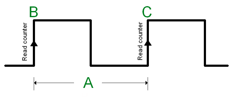
 The nearby graphic shows a hypothetical signal that carries frequency information. A is its period and the counter is read on the rising edge of the waveform indicated by points B and C. The counter values that are coincident with these rising edges are interpreted differently depending upon which is greater. Remember, the counter never stops counting, so there are three possibilities: C>B, C<B, or C=B. The first would occur if B is determined and the counter wraps back to zero and continues counting until C. Depending upon the relative values of B and C, the frequency of the applied signal (fs) is calculated as follows where fc is the counter’s clock that has a precise and known frequency:
Of course, if C=B then either no frequency signal is applied or the counter has wrapped one or more times to precisely the same value. Safeguards are built into the software to handle this case, as well as if C and B are not equal but the counter has overflowed. Let’s pass some examples through these equations to see how they respond. Assume that the counter clock frequency is 1 kHz and further assume that we’ve applied the same 50 pulse per gallon flow signal described in Part 2, the one that yields a 0.42 Hz frequency at a 1/2 gallon per minute flow rate. Remember that because of the very low frequency, and analog measurement approach is useless, and a traditional gated digital approach suffers from very long update rates.
In this example, A=2.38 seconds (the reciprocal of frequency.) Let’s assume a random value for B of 250 counts. Since the counter’s clock frequency is a precise 1 kHz, then over the next 2.38 seconds the counter increments 2,380 times to a value of 2,630 at point C. We know that C>B, pick the appropriate equation and substitute values to yield a signal frequency value of 0.42 Hz. Similarly, if we pick in initial value for B of 16,002, the final count at C will be 1,998. Since in this situation C<B we use the other equation to again calculate a value of 0.42 Hz for input signal frequency.
As is obvious in both examples, signal frequency value is determined using the ratiometric technique as soon as one cycle completes (2.38 seconds) compared to not making the measurement at all with the analog approach, or needing to wait 10 to 100 seconds for a reading using the gated digital approach. Further, since measurements can be made cycle-by-cycle, the ratiometric approach is greatly more responsive than the the analog technique.
I suppose that the only disadvantage of the ratiometric approach is that it requires on-board intelligence to determine which equation to use, and to make the frequency calculation. However, DATAQ Instruments starter kits are designed using micro controllers for which these tasks are routine.


 View Cart
 sales@dataq.com
 330-668-1444