Strain gage modules are used in data acquisition products to provide a supply (excitation) voltage to strain gage-based transducers and to amplify the output, which is then passed on to a data acquisition instrument such as the DATAQ Instruments DI-718B.
Often, when a test engineer or maintenance technician notices that the values they’re observing aren’t quite what they were expecting, or are all together outside the norm; their data acquisition hardware and/or software become suspect number one. Naturally, they begin to poke and prod, checking an input impedance here, an excitation voltage there. And while these measurements may seem relatively straight forward, that’s usually not the case. Take for example the DI-8B38 strain gage module. Once or twice a month a customer will call in and say “Hey, I measured across the excitation pins with a voltmeter and I see 17V! The sticker on the module says 10V excitation!” It’s true, measuring across the excitation pins of an unloaded DI-8B38 module will yield approximately 17V. It’s only when you connect a transducer to the module that you see 10V across the excitation pins.
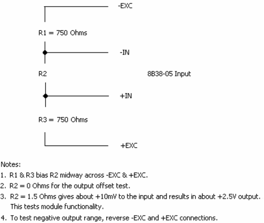
Due to the way that these signal condition modules are engineered, it’s often the case that a load or bias resistance must be applied in order to test the functionality. The OEM was in fact able to provide us with a procedure, using bias resistors, to verify proper operation of the DI-8B38 module (below).


 View Cart
 sales@dataq.com
 330-668-1444