(Note: A consolidated version of this topic that contains all six part can be found here)
Proper Shielding Techniques
We’ve established that isolation amplifiers do not perform well in the presence of large, high frequency common-mode voltages. Now we’ll focus on eliminating high level, high frequency signals before they ever reach the amplifier.
When connecting signals to your data acquisition instrument, proper shielding can make all the difference in the world. This is especially true when dealing with low level signals, where a little noise can render your data useless.
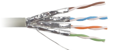
The shielding inside of a shielded cable is made up of strands of braided aluminum or copper (and sometime foil) that surround the connecting wires, insulating them from environmental noise. A “drain” wire is used to terminate the shield to ground. It is connected on either the sensor OR the instrumentation end of the cable (never both as this could result in a ground loop). Shielding is effective at reducing noise in single-ended or differential applications.
Twisting signal wires together to form a twisted pair is another method used to reduce noise. This is done so that neither wire is exposed to more noise than the other. As a result any noise that does make it to the amplifier is identical on both the + and – leads, and is therefore canceled out.


 View Cart
 sales@dataq.com
 330-668-1444