In the previous post we introduced our new WinDaq Engineering Units Scaling dialog box and solicited users for advice and guidance before making it a permanent part of the application. The new approach incorporated a Set Zero button that provided a simple way to compensate for sensors that exhibit a constant offset. We described it like this:
Finally, there’s the Set Zero button that allows you to instantly compensate for zero offsets from your measurement. How many times have you carefully calibrated a system only to see a slight offset in the result when you apply zero engineering units? It’s very common. You can apply zero engineering units to your sensor and then use the Set Zero feature to instantly force the offset to zero when you click the button.
Almost immediately we received a comment asking why we’d allow offsets that force the scaling only to zero, instead of a more general approach that allows an offset to any value within the ±EU range. Although we believe that the vast majority of applications will want to force an offset to zero, we could also envision those that may want to force non-zero offsets. So, making the feature more general-purpose in this manner was a good suggestion and one that we are currently implementing.
At first blush, though, you might wonder why a separate button is required to set an offset. Couldn’t you do that by applying a value other than zero for the lower value scale setting? That seems logical until you work though the math and discover that doing it that way actually changes the slope of the scaling line, and screws up your measurement everywhere within its dynamic range except at the initial offset value. To see why, let’s consider an example of a linear distance measuring device of some kind. It could be an LVDT, a string pot, LASER, or some other device, but it really doesn’t matter. Let’s assume that the device provides a linear output equal to 1 inch per volt, has a 5-inch full scale range, and is zero volts at zero inches of linear measurement.
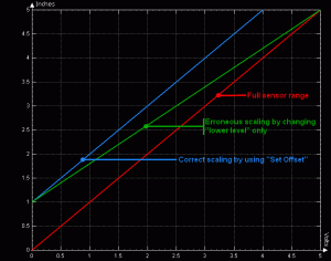
In the nearby graph, the red line describes the relationship between volts and distance for the full measurement range of our hypothetical sensor. The other two represent attempts to inject a 1 inch offset. One is correct while the other isn’t.
If you decided that you could properly offset the measurement just by changing the Lower Level scaling value, the relationship between volts and inches is described by the green line. Notice how the slope has changed and, in the process, destroyed the relationship between volts and inches across the entire measurement range except at the Lower Level value. Not good.
To make the offset work as planned you need to redefine the Lower Level and the Upper Level scaling values by the same amount. That approach preserves slope and ensures a constant offset across the measurement range.
In this manner, the Set Offset button saves mental arithmetic and the need to remember to change the Upper as well as the Lower scaling values to yield the desired result.


 View Cart
 sales@dataq.com
 330-668-1444