
 View Cart
 sales@dataq.com
 330-668-1444
Model DI-5B34-02
Isolated 0-100°C 2- or 3-wire RTD 5B-style Amplifier
Stock
- 0°C to +100°C (32°F to +212°F) measurement range
- Interfaces to 2- or 3-wire 100Ω Platinum, α = 0.00385 RTDs
- Linearizes RTD Signal
- High Level Voltage Outputs
- 1500 VRMS Transformer Isolation
- ANSI/IEEE C37.90.1-1989 Transient Protection
- Input Protected to 240VAC Continuous
- 160dB CMR
- 95dB NMR at 60Hz, 90dB at 50Hz
- CSA Certified
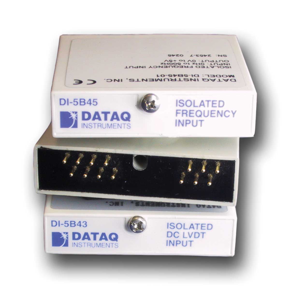
- View Dimensions and pinout
 Share
Share
Description
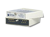
Each DI-5B34 RTD input module provides a single channel of RTD input which is filtered, isolated, amplified, linearized, and converted to a high level analog voltage output (see block diagram). This voltage output is logic switch controlled, which allows these modules to share a common analog bus without the requirement of external multiplexers.
The DI-5B modules are designed with a completely isolated computer side circuit which can be floated to ±50V from Power Common, pin 16. This complete isolation means that no connection is required between I/O Common and Power Common for proper operation of the output switch. If desired, the output switch can be turned on continuously by simply connecting pin 22, the Read-Enable pin to I/O Common, pin 19. RTD excitation is provided from the module by two matched current sources. When using a three-wire RTD, this method allows an equal current to flow in each RTD lead, which cancels the effects of lead resistances. The excitation currents are very small (0.25mA for 100Ω Pt and 120Ω Ni, and 1.0mA for 10Ω Cu) which minimizes self-heating of the RTD.
Signal filtering is accomplished with a six-pole filter which provides 95dB of normal-mode-rejection at 60Hz and 90dB at 50Hz. Two poles of this filter are on the field side of the isolation barrier, and the other four are on the computer side. After the initial field-side filtering, the input signal is chopped by a proprietary chopper circuit. Isolation is provided by transformer coupling, again using a proprietary technique to suppress transmission of common mode spikes or surges. The module is powered from +5VDC, ±5%.
A special input circuit on the DI-5B34 modules provides protection against accidental connection of power-line voltages up to 240VAC.
Accessories
Description
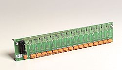
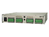
16-channel backplane for 5B modules. Each module has its own analog bus. For use with DI-5B Modules.
Description
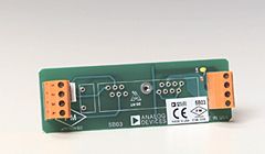
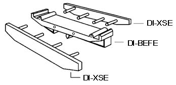
Base element with snap foot required for use with models DI-5B03 and DI-5B04 Backplanes. For use with DI-5B Modules.
Description
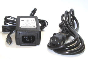
5V DC Power Supply for use with both DI-5B and DI-8B Backplanes.
Description
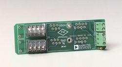
Side element required for use with models DI-5B03 and DI-5B04 Backplanes. For use with DI-5B Modules and Backplanes.
Specifications
| Input Range: | 0°C (32°F) to +100°C (+212°F) |
| Output Range: | 0 to +5V |
| Accuracy: | ±0.13°C (Includes conformity, hysteresis, and repeatability.) |
| Input Resistance: | Normal: 50MΩ Power Off: 40kΩ Overload: 40kΩ |
| Input Protection: | Continuous: 240Vrms max Transient: ANSI/IEEE C37.90.1-1989 |
| Sensor Excitation Current: | 0.25mA |
| Lead Resistance Effect: | ±0.02°C/Ω (“Ω” refers to the resistance in one lead.) |
| CMV, Input to Output: | Continuous: 1500Vrms max Transient: ANSI/IEEE C37.90.1-1989 |
| CMR (50 or 60Hz): | 160dB |
| NMR: | 95dB at 60Hz, 90dB at 50Hz |
| Conformity Error: | ±0.05% Span |
| Stability: | Input Offset: ±0.02°C/°C Output Offset: ±20µV/°C Gain: ±50ppm of reading/°C |
| Noise: | Input, 0.1 to 10Hz: 0.2µVrms Output, 100kHz: 200µVrms |
| Bandwidth, –3dB: | 4Hz |
| Response Time, 90% Span: | 0.2s |
| Output Range: | 0V to +5V |
| Output Resistance: | 50Ω |
| Output Protection: | Continuous Short to Ground |
| Output Selection Time (to ±1mV of VOUT): | 6µs at Cload = 0 to 2000pF |
| Output Current Limit: | ±14mA max |
| Output Enable Control: | Max Logic “0”: +0.8V Min Logic “1”: +2.4V Max Logic “1”: +36V Input Current, “0,1”: 0.5µA |
| Power Supply Voltage: | +5VDC ±5% |
| Power Supply Current: | 30mA |
| Power Supply Sensitivity: | 0.2°C/V |
| Environmental: | Operating Temperature: -40ºC to +85ºC Storage Temperature: -40ºC to +85ºC Relative Humidity: 0 to 95% Noncondensing RFI Susceptibility: ±0.5% Span Error at 400MHz, 5W, 3ft |
| Mechanical Dimensions: | 2.28" × 2.26" × 0.60" (58mm × 57mm × 15mm) |
* At standard 60Hz factory calibration. For 10 to 100% rated span. Add an additional 0.25% error for 0 to 10% Span measurements. Accuracy includes nonlinearity, hysteresis and repeatability but not source or external shunt inaccuracy (if used).
Articles
Bandwidth Considerations for DI-5B and DI-8B Signal Conditioning Modules
Learn the Importance of Isolation In Four Easy Lessons
How To Calibrate Strain Gage-Based Transducers Using DI-5B38 Strain Amplifiers