How To Connect and Calibrate Thermocouples Using DI-8B47 Series Amplifiers
Thanks to the American National Standards Institute (ANSI), thermocouple wire is color coded to indicate thermocouple type and polarity. This takes the guesswork out of connecting thermocouple wires to your DI-718B, DI-718Bx, or DI-788.

In this example, we’ll show you how to connect and calibrate a K-type thermocouple using a DI-718B, with a DI-8B47K-13 amplifier plugged into channel three.
We’ll begin by inserting a cold junction compensation jumper (included with your DI-718B, DI-718Bx, or DI-788.
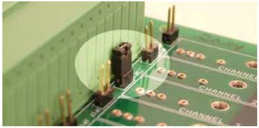
A cold junction compensation jumper placed on channel 3
Next, we’ll insert the DI-8B47K-13 amplifier and connect the positive and negative thermocouple wires to In+ and In- respectively. If you reverse the polarity, increasing temperatures will display like they’re decreasing and visa versa.
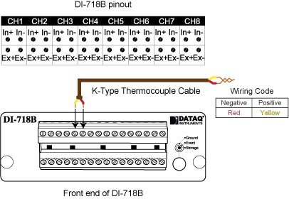
With our thermocouple connected; we'll use Engineering Unit Settings in WinDaq to display temperature.
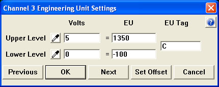
We'll begin by selecting 'Engineering Unit Settings' from the 'Edit' pull-down menu.
Since we know that the DI-8B47K-13 has a full scale output of 0 to 5 volts and a measurement range of -100°C to 1350°C (printed on the side of the amplifier); we'll enter 0 (zero) for Lower Level Volts and -100 for Lower Level EU. We'll enter 5 for Upper Level Volts and 1350 for Upper Level EU. For EU Tag, enter "C".
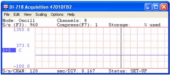
Finally, to display the actual measurement range of the amplifier; we'll select 'Limits' from the 'Scaling' pull down menu. Enter 1350 for the Top Limit and -100 for the Bottom Limit.
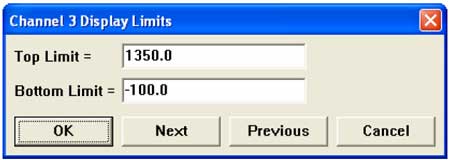
Channel 3 is now calibrated to display temperature over the full-scale range of the DI-8B47K-13!
Additional Reading:
Ambient Temp Affects Thermocouple Measurement Accuracy
Maximum Thermocouple Wire Length


 View Cart
 sales@dataq.com
 330-668-1444